Students: Dane Karlsen, Sean Obanion, Benko Nicholas
Faculty Advisor: Bayaner Arigong
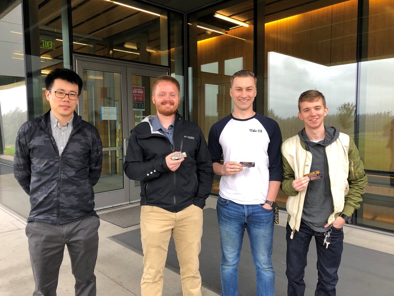 From left to right, Bayaner Arigong, Dane Karlsen, Nicholas Benko and Sean OBanion. Team photo courtesy of WSU.
Wireless power has largely been disregarded as either an impossible fantasy or uselessly ineffective. The notion of sending power through the air is an idea so ridiculous it is rarely explored, even in science fiction. Despite this, the Cota technology, by Ossia is prepared to power the next generation of devices. Even if the world does not know it yet. Wearable devices are one of the many markets which can profit immensely from the Cota Real Wireless Power technology. To demonstrate the usefulness and capability of wirelessly powered devices, Ossia sponsored a capstone project at Washington State University Vancouver to develop a wirelessly powered wearable device. The device was required to be compact, require no batteries, and monitor a simple biometric of the wearer. After considering several options, the capstone group settled on a device which would detect when the wearer falls. Fall detection was chosen due to its simplicity and the low power consumption of the components required to detect and measure the users motion characteristics. The device was intended to improve the bulky and stigmatized fall detectors which are currently available to the elderly today.
The main functional components of the project included a TI MSP430 microcontroller, a TDK accelerometer, and an ST Bluetooth module. To detect a fall, the accelerometer gathers acceleration data which the microcontroller (MSP) analyzes. If a fall is detected, the Bluetooth module sends an alert signal to a smartphone or other device.
Designing a circuit to harvest and store RF power was a large step in the project. The main components of the power circuit were an antenna, rectifier, boost converter, supercapacitor, and a buck converter. The general components were chosen based on suggestions from one of Ossia’s project sponsors. These include a Linx nSP antenna, a TI energy harvester chip, and the initial design of the rectifier circuit. The TI harvester chip bundles the boost, buck, and supercapacitor functionality and provides other features such as a voltage-good indicator. Due to the relatively high cold-start voltage of the harvester, an array of optional photodiodes was also included in the first prototype. A low dropout regulator (LDO) was added to the harvester’s output due to concerns with the stability of the output voltage.
After the prototype was assembled, coding and debugging began. The MSP and the accelerometer were configured to flash an onboard LED when motion above a threshold is detected. The MSP was set to sleep until woken by the accelerometer and the accelerometer was configured to a low power mode. All of this was designed to minimize power consumption.
With additional time, there are several improvements which could be made. First and foremost, testing and tuning of the RF power harvesting circuit could be performed to determine how well the device could run off wireless power. Also, improvements to the design and layout of the PCB could reduce its size. A more complex data analysis algorithm could be implemented that evaluates the sensor’s data over time to improve fall detection accuracy. Finally, implementation of the Bluetooth capability proved more difficult than anticipated and still needs to be completed.
Through the process of this project the capstone group gained valuable experience in many engineering subjects such as: part selection, PCB design, RF circuit design, PCB manufacturing, and embedded systems. Although the first prototype has needed improvements, with a second PCB design iteration, access to a network analyzer, and a few more weeks, the group is confident their design would work as intended.
The capstone team is grateful to Ossia and the project sponsors, Doug Stovall and Cosan Caglayan, for giving them the support and opportunity to work on such a fascinating project. 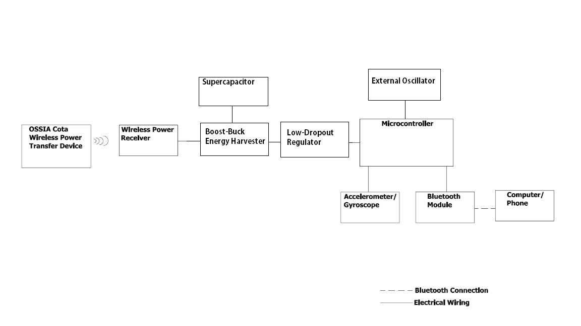 Fig. 1. System architecture block diagram
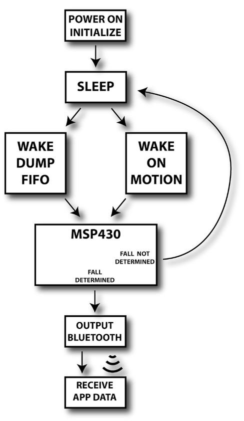
Fig. 2 Flow chart of system program
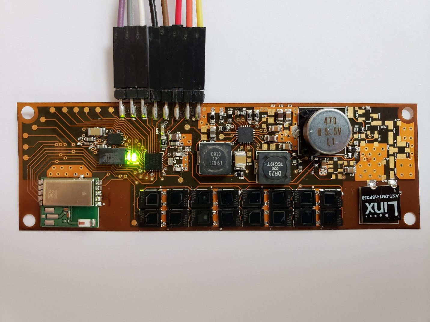 Fig.3 Prototype of demo using flexible PCB


